Design and selection guides
Design

bigHead fasteners can be embedded into laminar FRP composite structures using four proven configurations. This guide provides the essential design rules for doing so effectively. It outlines the geometric requirements, laminate thickness rules, reinforcement considerations, spacing guidelines and indicative mechanical performance for each configuration.
bigHead fasteners can be embedded in FRP laminates using four configuration types (figure 1):
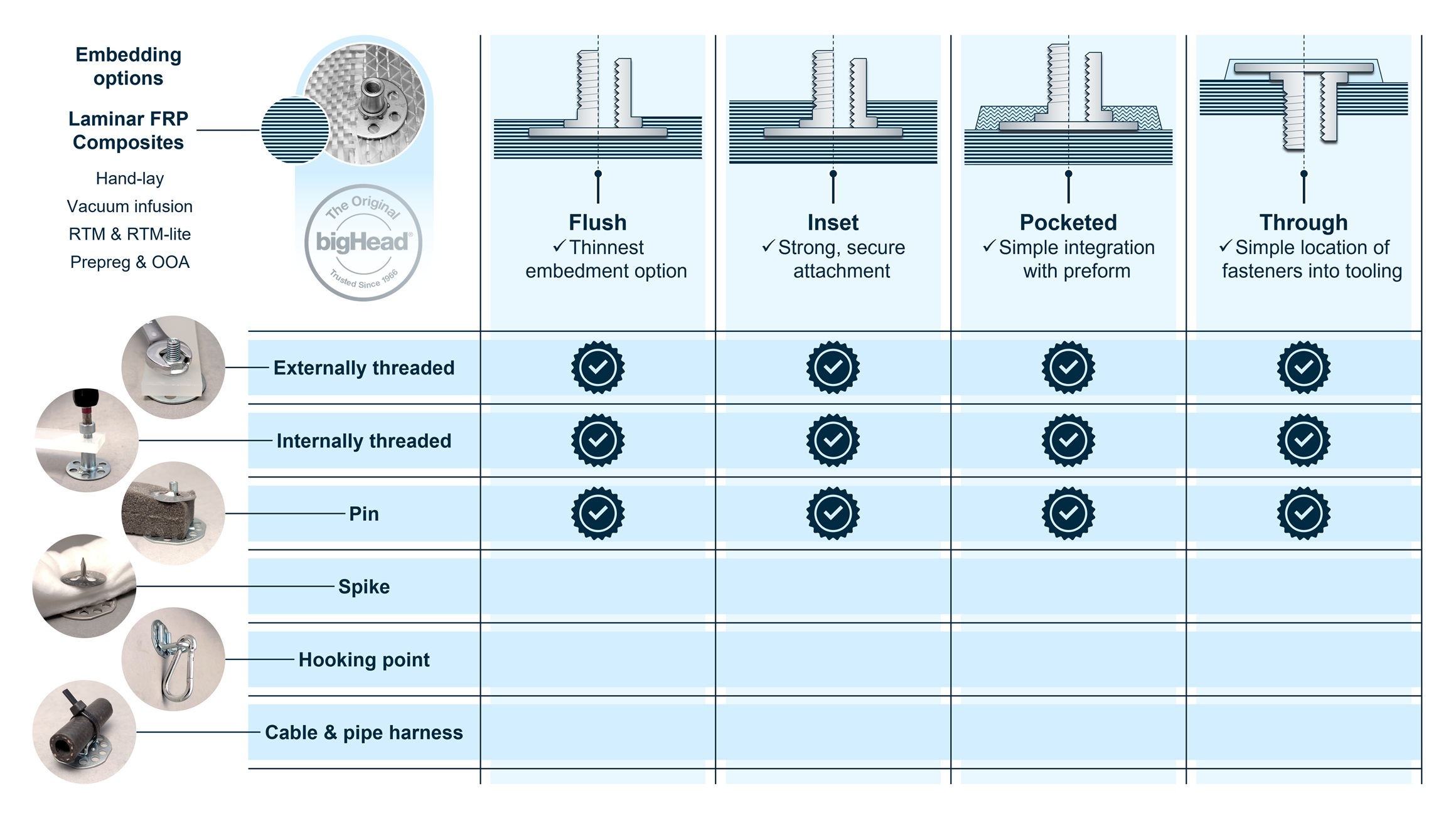
Figure 1 – applicable configurations and fastening functionalities for bigHead fasteners and laminar FRP composites
Compatible fastener types are:
When embedding internally threaded fasteners, it is best to use blind installation (where screws do not pass through). Blind Head products are typically used (e.g. F2 B30 or SF2 T38A).
Sighted embedment (where screws pass through) requires additional consideration. We can advise on the optimal solution for your configuration – get in touch.
A flush installation is achievable only when the laminate thickness at the fixing interface matches the fastener’s L1 dimension.
To determine the matching thickness:
To achieve a flush configuration:
Total laminate thickness (without the bigHead) ≥ L1 + 1 ply
This ensures proper consolidation and a level surface finish.
If the laminate is thinner than L1, the shoulder/flange will sit proud of the laminate. Reduced consolidation may occur depending on tooling.
If the laminate is thicker than L1, the fastener will sit recessed into the laminate or inset within the matrix material, depending on the shutoff strategy.
Example 1
Example 2
Example 3
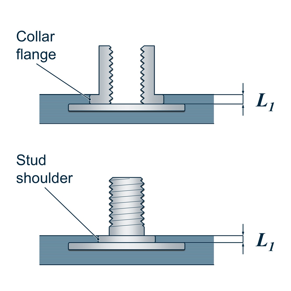
Figure 2 – L1 definition for laminate thickness around collar (upper) and stud (lower) fixing interface
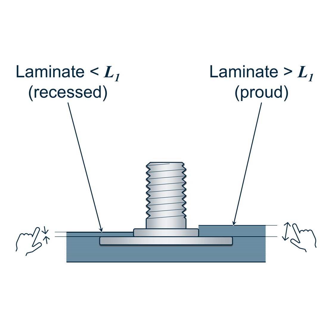
Figure 3 – recessed and proud fixing interfaces arising from laminate thickness mismatch
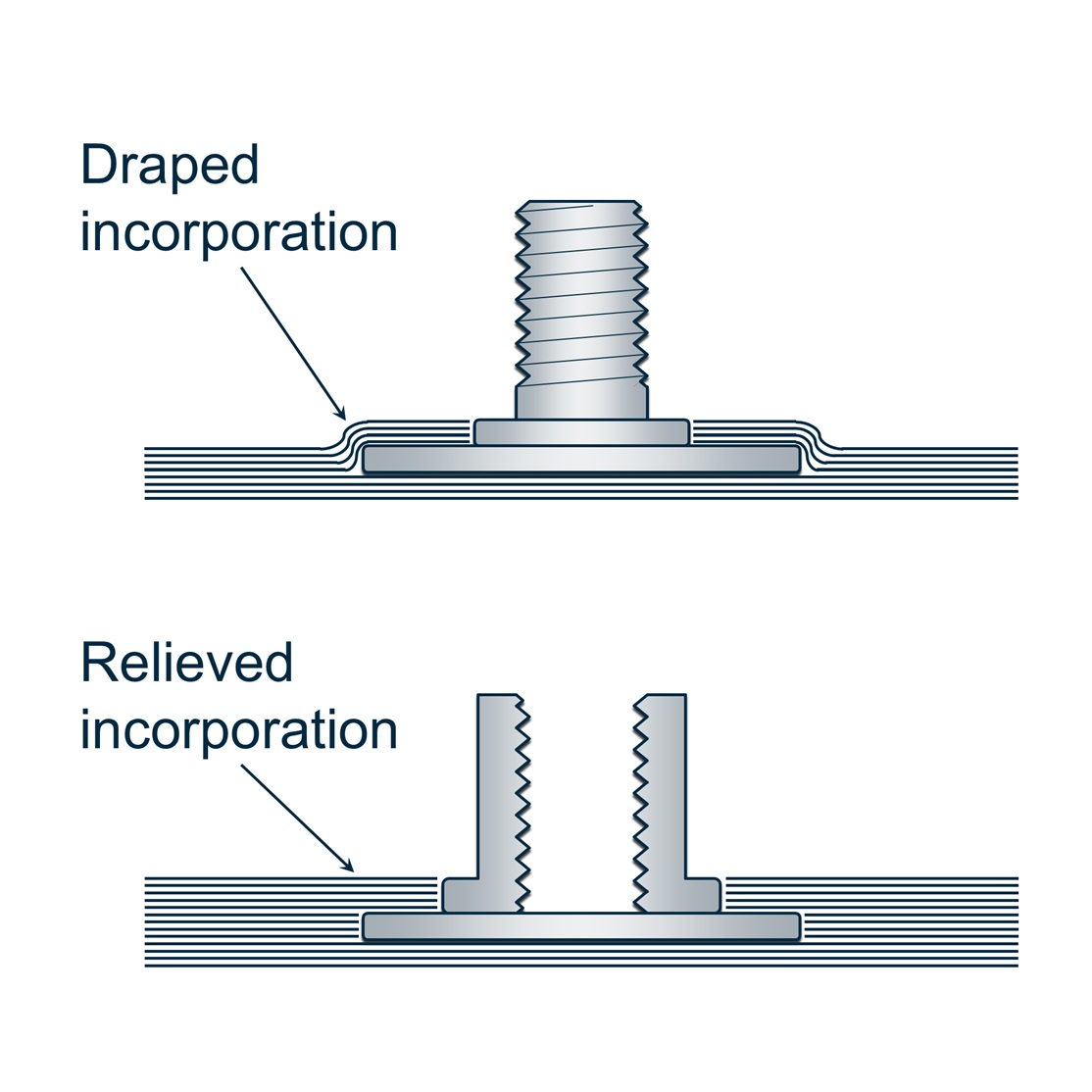
Figure 4 – draped (upper, stud example) and relieved (lower, collar example) laminate incorporation approaches
Inset configurations require laminate thickness greater than the embedded fastener geometry. Specifically:
Plus:
Generally, inset configuration is only practicable for laminate thicknesses greater than 3 mm.
Laminate thickness > L1 + T
Example 1
Example 2
These are general guidelines, as the exact pocket geometry will depend on the tooling and shutoff strategy.
For both reinforced and unreinforced pockets, the pocket thickness must be at least equal to the embedded bigHead fastener sections:
Plus:
Pocket thickness ≥ L1 + T
For reinforced pockets, allow a margin around the Head of at least 10 mm or 0.5 × Head dimension (whichever is greater), as shown in figure 2.
This ensures sufficient reinforcement overlaps and mechanical performance.
To calculate the reinforced pocket dimension for a given Head dimension:
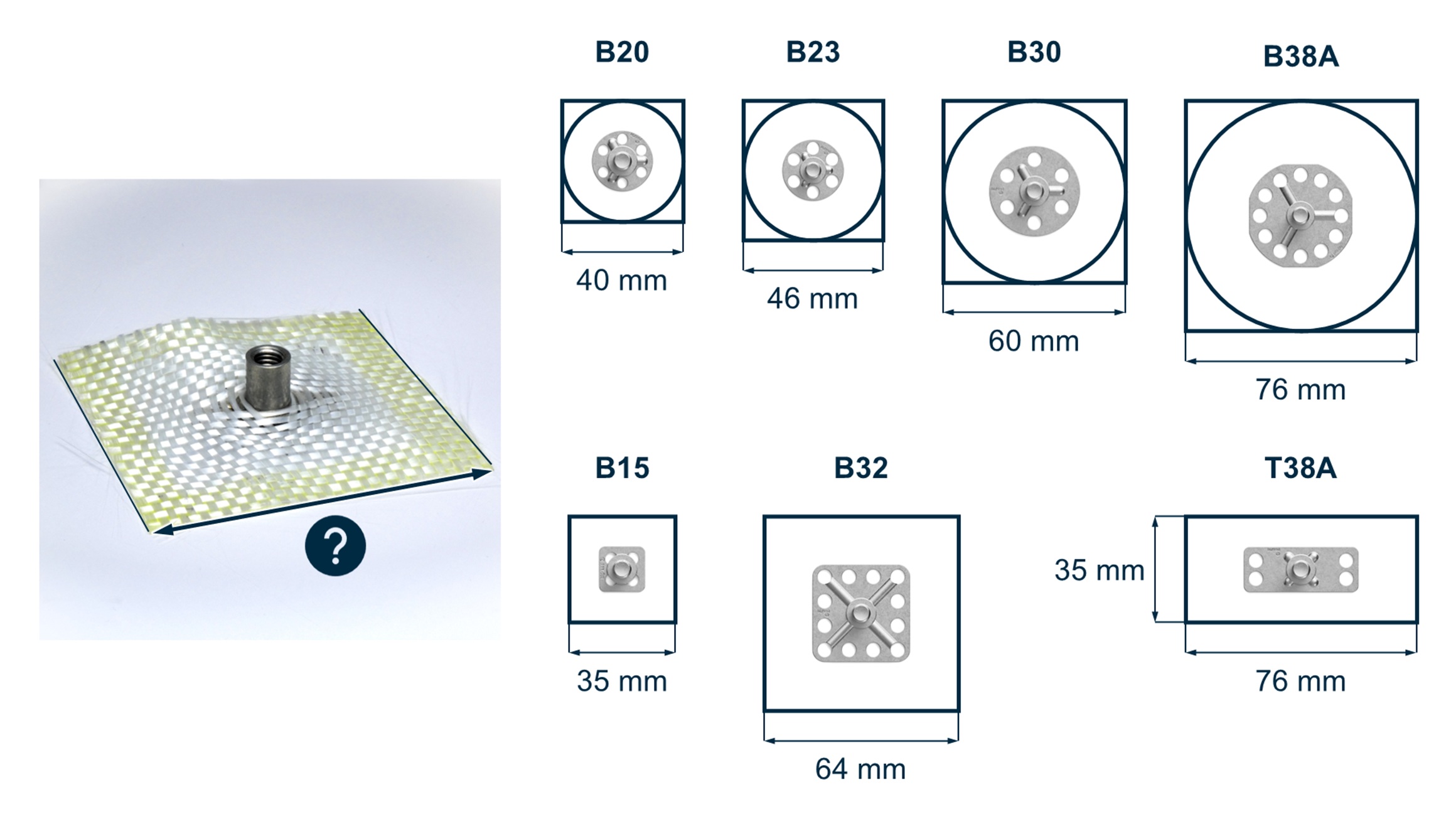
Figure 5 – minimum recommended reinforced pocket sizes for bigHead product types
Unreinforced pockets should have a size margin around the Head equivalent to at least the shoulder or flange height (L1).
This ensures a consistent minimum resin/polymer thickness around the fastener.
To calculate the unreinforced pocket dimension for a given Head dimension, double the L1 value and add it to the Head dimension.
Example 1
Example 2
Through installation is achievable by incorporating the fastener sections within the reinforcement plies (figure 6), or within a pocket (figure 7).
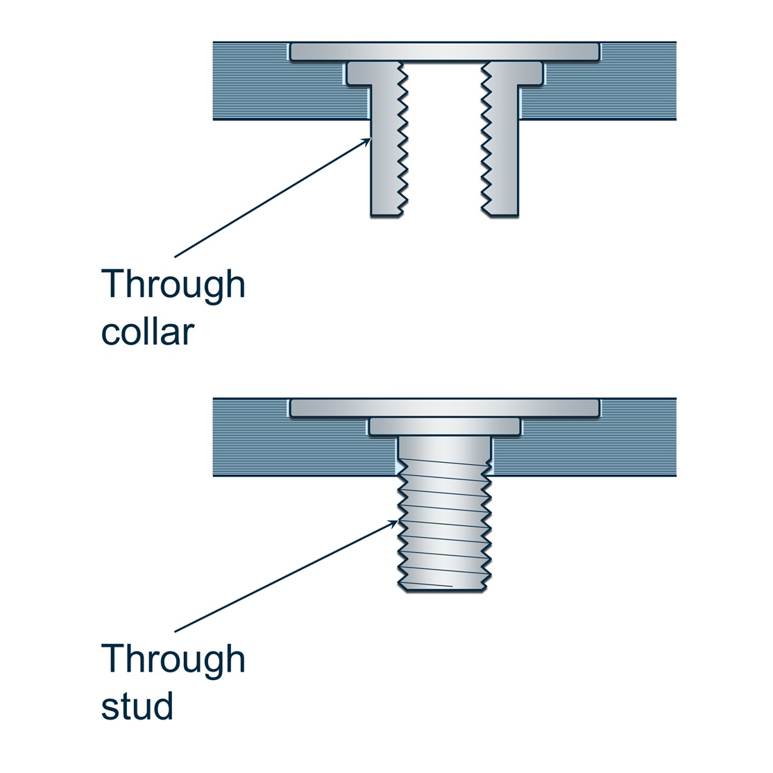
Figure 6 – through collar (upper) and stud (lower) installations in laminar material
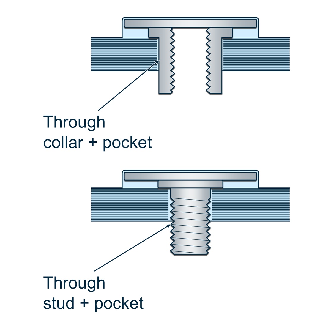
Figure 7 – through, pocketed collar (upper) and stud (lower) installations in laminar material
Unreinforced pocket installation is a simple way to incorporate bigHead fasteners in a through configuration without needing to prepare holes or cutouts.
Tissue or veil layers act as surface-conforming materials that prevent fastener breakthrough from the laminate or direct contact with gelcoats – not structural reinforcement.
If no application‑specific spacing rules exist, use the following simplified rules based on established hole‑spacing practice [A].
A: Niu, Michael ChunYung. Composite Airframe Structures: Practical Design Information and Data. Hong Kong: Conmilit Press, 1992. ISBN 9627128066
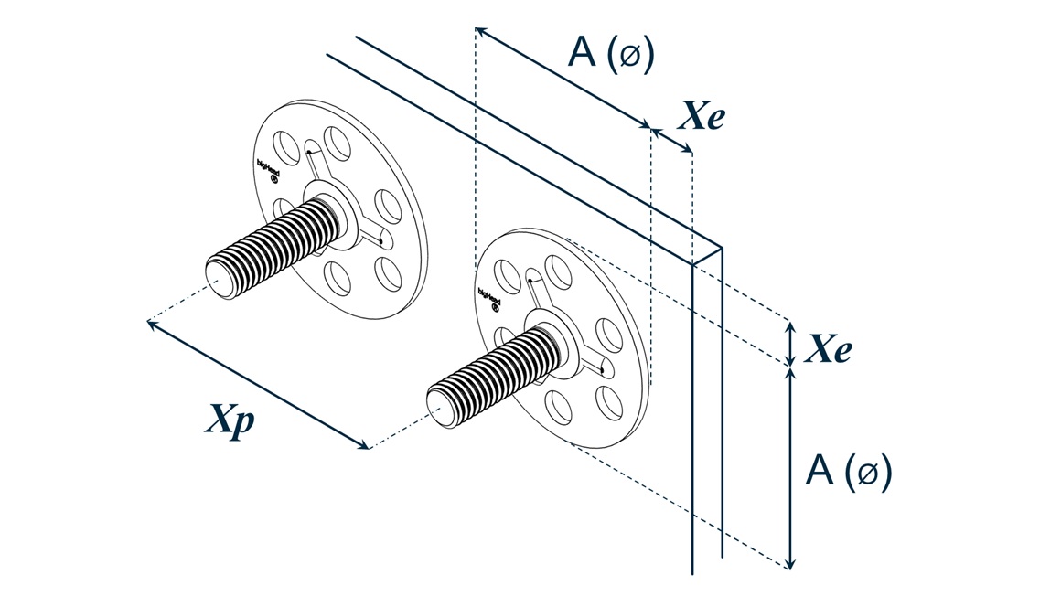
Figure 8 – edge (Xe) and pitch (Xp) spacing definition for round bigHead product types

Figure 9 – edge (Xe b & c) and pitch (Xp) spacings for rectangular bigHead product types
Minimum distance from laminate edge to centre axis of the bigHead fixing:
Xe ≥ max(3D1, 1.5 × Head dimension)
Where:
Minimum centre‑to‑centre distance between fasteners:
Xp ≥ max(5D1, 1.5 × Head dimension)
Where:
Example 1
bigHead M1 T38A M8 × 25
Parallel to B:
Parallel to C:
Example 2
bigHead SF2 B30 M12 × 20
Mechanical performance depends on the fastener type and size, the laminate materials, and the embedment configuration.
The following indicative performance values are based on our tests using fasteners with an M6 thread and B30 Head, embedded in a 4.8 mm quasi‑isotropic glass fibre/vinylester laminate.
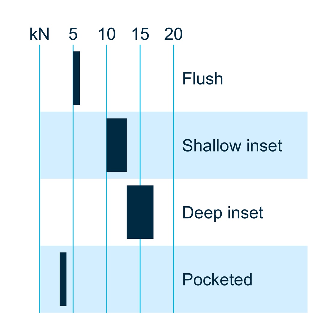
Figure 10 – typical pull-out (axial loading) performance of embedded bigHead configurations in laminar FRP
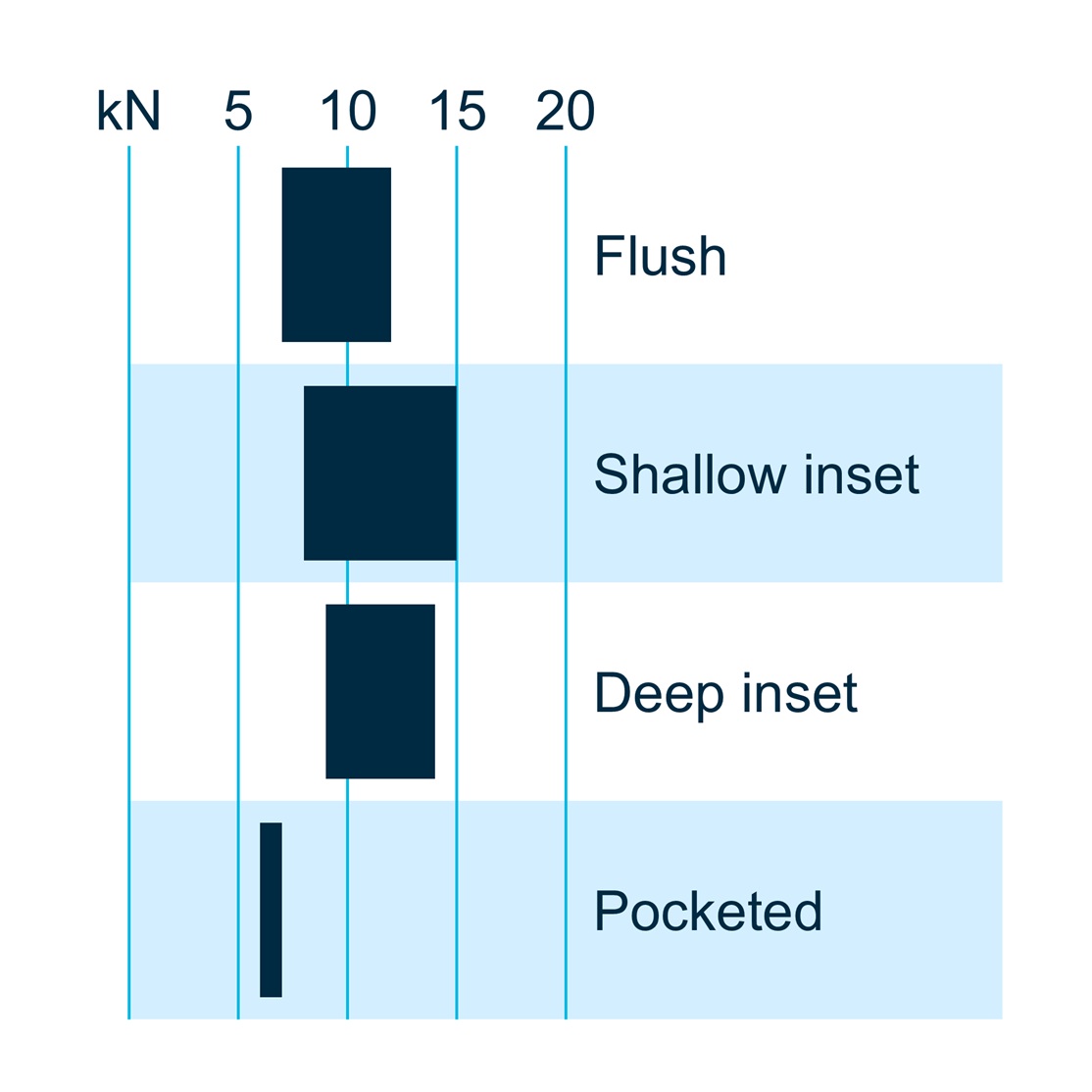
Figure 11 – typical shear-out (shear loading) performance of embedded bigHead configurations in laminar FRP
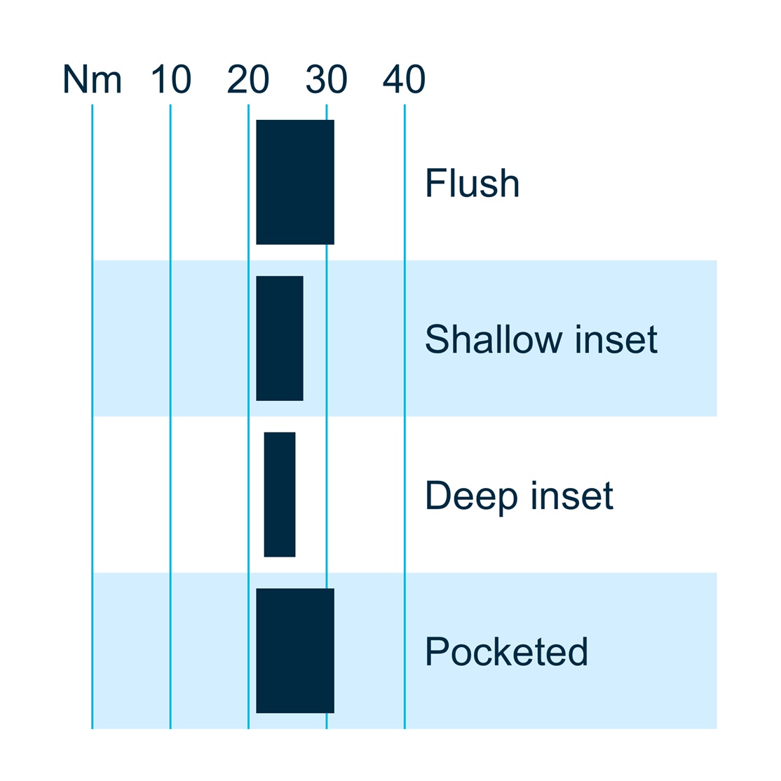
Figure 12 – typical torque-out (torsional loading) performance of embedded bigHead configurations in laminar FRP
Load to failure:
Load to failure:
These values indicate the maximum rotational resistance of the embedded fastener. They do not represent permissible tightening torque.
Torque-out failures typically occur in the fastener itself, so values are similar across configurations.
FRP materials may show matrix cracking before the fastener reaches its peak load.
Because safety factor and damage tolerance requirements vary by application, we can’t specify whether designs should be based on crack initiation load or peak load.
Due to the wide range of composite constructions, we also can’t provide crack onset data for embedded bigHead fastening configurations. These thresholds must be established experimentally for each material system.
For more information about testing our products, see our testing and evaluation guides. For specific performance data or support, get in touch.
Flush works for thin laminates.
Inset generally offers higher strength where laminate thickness allows.
Pocketed is useful when reinforcement continuity is required.
Through configurations suit applications needing a balance of maximised embedment strength with minimum reinforcement/preform disruption.
Compare the laminate thickness at the fixing interface with the fastener’s L1 (shoulder/flange) and T (Head) values.
Flush installations require the laminate thickness to match L1.
Inset installations require thickness > L1 + T.
Reinforced pockets generally offer better load distribution and mechanical performance, especially for pull-out and shear.
Unreinforced pockets are acceptable where loads are modest or local reinforcement would be complex to implement.
Yes – but for sighted (screws pass through) installations, we recommend contacting us first. These cases often require special considerations for configuration geometry, laminate consolidation, and ingress sealing.
No. Torque-out values reflect rotational failure of the embedded fastener and do not represent the safe tightening torque for installing a nut or screw.
Tightening torque must be determined separately based on the specific joint design.