Each test type applies load in a different direction and creates different load paths and failure mechanisms. Because the loading response is fundamentally different in each case, installation strength values from axial, shear, and torsional tests cannot be compared directly.
Installation strength evaluation helps you understand how a bigHead fastener performs once installed as part of a fastening system – not as a standalone fastener.
This guide helps you identify the predominant load case (axial, shear, or torsional), select appropriate test methods, and interpret results comparatively, so that you can make informed design decisions.
No single test captures real-world behaviour. Meaningful evaluation focuses on trends, failure modes, and system interactions, supported by representative testing where confidence is critical.
Key takeaways
- Installation strength is a system response, comprising the bigHead fastener, substrate, and adhesive (where used), not a standalone fastener property.
- Different installation configurations create different load paths and failure modes. Results cannot be compared across configurations.
- Axial, shear, and torsional tests each isolate a single dominant load case and answer different evaluation questions.
- Coupon-scale test results are most valuable for comparative assessment, not for defining absolute performance limits.
- For real-world assemblies, combined test strategies and representative small-element or full-scale structure specimens are often required.
Purpose and scope of this guide
This guide helps you evaluate the installation strength of bigHead fasteners in embedded and surface-bonded configurations.
This guide is for:
- Understanding when and why different installation and assembly configurations require different evaluation approaches.
- Supporting application-relevant performance evaluation and realistic expectations for different assembly designs.
- Clarifying the distinction between installed fastening system evaluation and standalone fastener product testing.
This guide is not:
- A method for evaluating standalone fastener loadability.
- A qualification or certification standard.
- A target-setting methodology for defining performance specifications or pass/fail thresholds.
- A replacement for application-specific, industry-standard or regulatory evaluation procedures.
This guide applies to internally and externally threaded bigHead fasteners, and highlights where principles can extend to other fixing types.
The guidance is not specific to material concepts, but does indicate where special cases exist for material concepts.
Installation strength as a system response
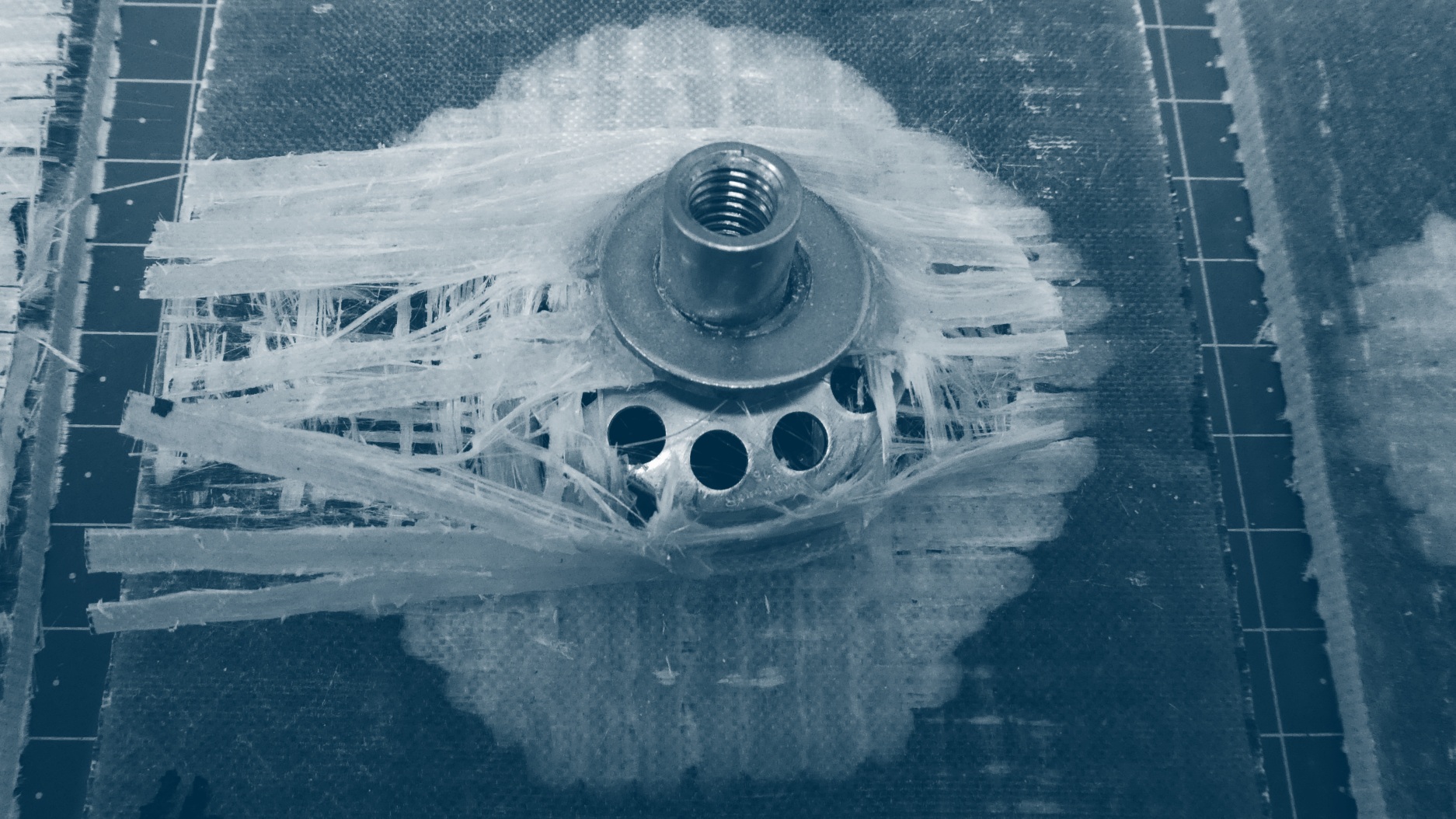
Installation strength depends on how the fastener, substrate, and adhesive (if used) interact under load. It is not equivalent to standalone fastener strength.
Installation configurations covered in this guide
Embedded configurations:
- Flush
- Inset
- Pocketed
- Through
- Socket
Surface-bonded configurations:
- Blind
- Through
- Socket
Each configuration produces different load paths and failure mechanisms. Therefore, when evaluating installation strength:
- Loading arrangements must reflect the specific configuration.
- Results cannot be compared across configurations.
- Interpretation must focus on the installation, not other elements of the fastening system.
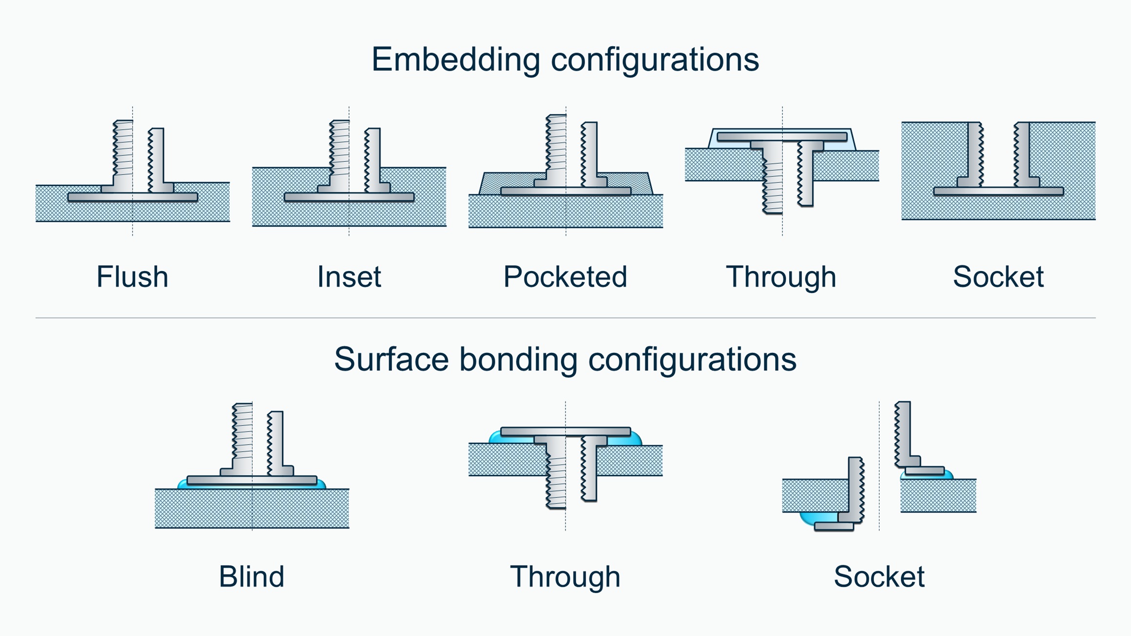
Applicable stud (M1/SM1) and collar (F2/SF2) configurations for installation strength evaluation guidance”
Load paths and failure modes
There are three main load paths within a bigHead fastener installation. Real-world loading often involves combinations of the three.
Axial load
- What it is: Axial load acts along the fastener axis, pulling the fastener away from the substrate.
- How it is evaluated: Typically by applying a tensile force to the fastener while the substrate is retained. The load is applied in the opposite direction to screw entry or nut fitment.
- What it reveals: Characterises pull-off, pull-out, or pull-through responses, depending on configuration.
- Configuration notes: Expected failure modes vary significantly between embedded and surface-bonded installations.
Shear load
- What it is: Shear load acts perpendicular to the fastener axis, causing sideways movement between fastener and substrate.
- How it is evaluated: Typically by applying a force perpendicular to the fastener axis while the substrate is retained.
- What it reveals: Characterises shear-off or shear-out responses, depending on configuration.
- Configuration notes: Shear-off failure typically only occurs with surface bonded installations.
Torsional load
- What it is: Torsional load is rotational force acting about the fastener axis. It mainly arises during assembly for threaded fasteners.
- How it is evaluated: Typically by applying rotational force to the fastener.
- What it reveals: Characterises torque-off or torque-out responses. Failure occurs when rotational loads exceed installation strength.
- Configuration notes: Torsional loading rarely occurs under normal service conditions. Do not confuse the torsional loading response of the fastener and substrate connection with the torque-tightening and preload response of the entire fastening system.
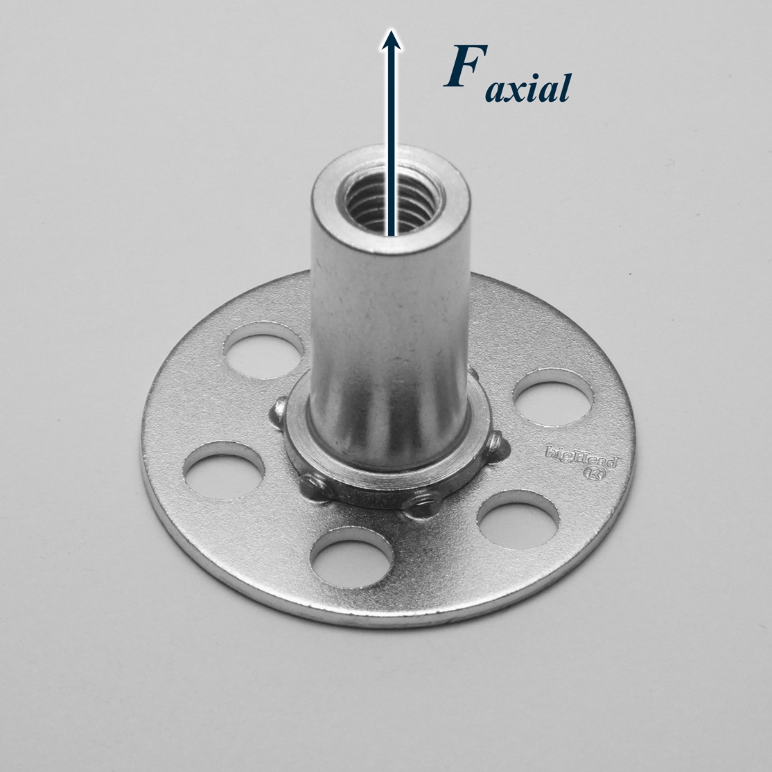
Axial loading case for bigHead fasteners
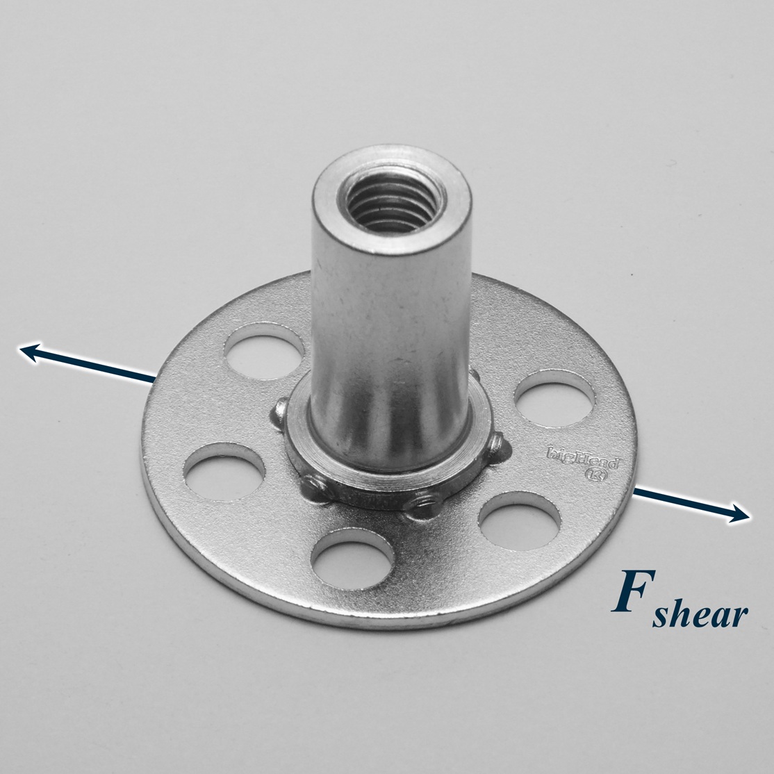
Shear loading case for bigHead fasteners
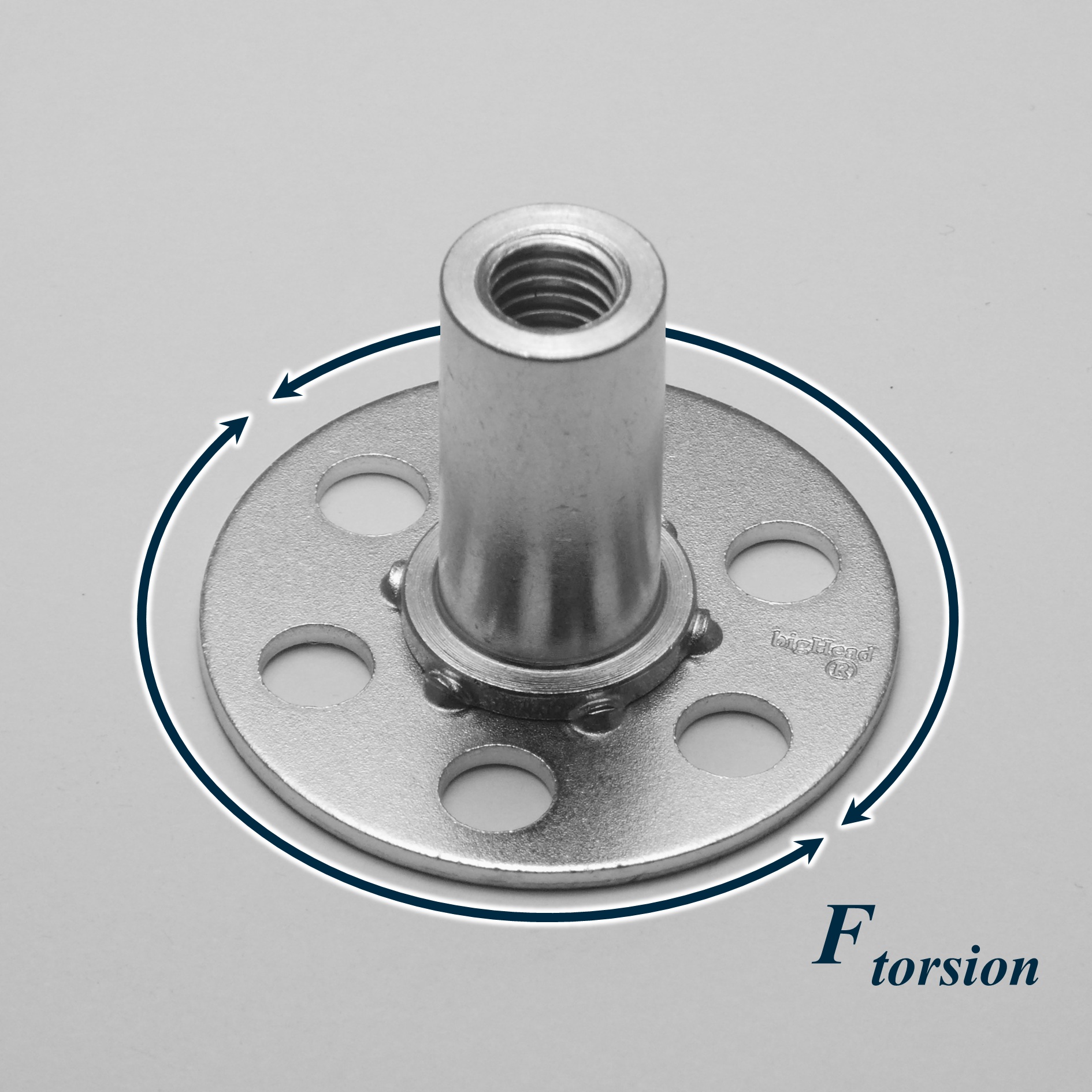
Torsional loading case for bigHead fasteners
Defining the dominant load case(s)
Correct evaluation depends on identifying which load case governs performance during service or assembly.
Service loads vs installation loads
Service loads occur during intended or foreseeable application usage. They may be static or cyclic, depending on the operational parameters of the end-use application.
Installation loads usually arise from torque-tightening reactions (torsional load), or axial forces as components are pulled together during assembly.
The scale, direction and likelihood of these different loads – or which one is predominant at a given stage – depends on how the assembly items interact with each other, and how the fastening constrains them.
Identifying the predominant load direction
To identify the predominant load direction in a bigHead fastener installation, consider:
- How the fastened assembly components interact with each other.
- How those interactions introduce load into the fastener.
In most cases, the dominant load direction corresponds to the relative movement tendency between the connected components.
Shear-dominated loading
Where components tend to move relative to each other parallel to the fastened surface, this creates a shear load condition within the fastener installation.
Axial-dominated loading
Where components tend to move away from each other perpendicular to the fastened surface, this creates an axial load condition within the fastener installation.
Torsional loading
Where rotational forces act between the fastener and the installation surface, this creates a torsional load condition within the fastener installation. For threaded fasteners, this usually happens during assembly, not in service.
Cleavage and bending effects
Where components separate in a way that introduces local bending as well as axial tension, this creates a combined loading condition. Axial loading is usually the predominant contributor for evaluation purposes.
Combined and off-axis loading
Where loads act in multiple directions simultaneously, this creates a complex combined loading condition. In these cases, mechanical performance depends on the strength and stiffness of the complete fastening system. Evaluating this behaviour therefore requires system-level assessment rather than fastener installation strength testing.
Choosing an evaluation method
Coupon-scale testing is the first step in evaluating bigHead fastener installation strength, because it isolates performance in a single dominant load direction. This helps identify strengths and weaknesses in axial, shear, or torsional loading, without the complexity of full-assembly behaviour.
However, coupon-scale results do not represent complete system performance. When testing small-element or full-scale specimens that reflect real-world geometry and load paths, multiple load cases act together and interact. Under these conditions, it becomes very difficult to isolate the specific cause of good or poor performance.
A complete evaluation therefore typically follows a pyramid approach:
- Many coupon-scale tests to understand dominant load-case behaviour and refine the design.
- A few small-element tests to validate assumptions and calculations.
- One or two full-scale tests to confirm that the entire fastening system performs as expected under representative conditions.
Because coupon-scale testing is the starting point, the next sections outline when to evaluate bigHead installations under axial, shear, and torsional loading.
When to evaluate installation strength by axial testing
Axial testing evaluates how adhesive-bonded or embedded bigHead fastener installations respond to tensile loading acting along the fastener axis.
For information on test arrangements and procedures, see our axial testing guide.
The appropriate axial test arrangement depends on the installation configuration, as load is introduced differently in each case:
- Surface‑bonded (blind) installations: Axial testing evaluates pull‑off behaviour, which is sensitive to adhesive selection, surface preparation, cure quality, and substrate surface integrity.
- Embedded installations: Axial testing evaluates pull‑out behaviour, characterising how the fastener geometry interacts with the surrounding substrate material.
- Surface‑bonded socket and through‑bonded installations: Axial testing evaluates pull‑out or pull‑through behaviour, depending on the load-introduction arrangement and fastener type.
What axial testing is most useful for
Axial testing is particularly effective for:
- Identifying installation-related sensitivities, such as surface preparation quality or embedment consistency.
- Comparing relative performance trends between different substrates, adhesives, or bigHead product variants.
- Understanding likely failure modes under axial tensile loading.
- Providing a conservative indication of axial load limitations of the installation.
Limitations of axial testing
Axial testing evaluates responses to a single dominant load case and does not represent the full mechanical behaviour of a bigHead fastener in a real assembly. In particular:
- High axial strength does not imply equivalent resistance to shear or torsional loading.
- Axial test results should not be used where service loads predominantly impart shear forces into the fastener.
- Under combined or off-axis loading, mechanical performance is governed by the complete fastening system, so axial testing should form only one part of a broader evaluation strategy.
When to evaluate installation strength by shear testing
Shear testing evaluates how a bigHead fastener installation responds to loads acting perpendicular to the fastener axis, where forces are transferred laterally into the substrate or bonded interface.
Interpretation of shear testing depends on the installation configuration, as shear load is introduced and resisted differently in each case:
- Surface-bonded (blind) installations: Shear testing evaluates shear-off behaviour, which is sensitive to adhesive stiffness, bond area, substrate surface integrity, and local substrate compliance.
- Embedded installations, surface-bonded socket, and through installations: Shear testing evaluates shear-out behaviour, characterising how fastener geometry, substrate material, and adhesive (where used) interact under lateral loading.
In all cases, shear-test arrangements must introduce load in a way that reflects the intended fastening design and does not artificially alter the failure mode.
What shear testing is most useful for
Shear testing is particularly effective for:
- Assessing installation performance where service loads act in‑plane with the substrate.
- Comparing relative performance trends under shear‑dominated loading.
- Understanding failure modes where load is distributed across the fastener-substrate interface.
- Supporting design decisions where shear is the governing load case and axial loading is secondary.
Shear testing often produces higher apparent strength values than axial testing. Results should not be compared directly between test types.
Limitations of shear testing
Shear testing evaluates responses to isolated lateral loading and does not capture full assembly behaviour. In particular:
- High shear strength does not imply adequate axial or torsional load resistance.
- Shear is not appropriate where axial separation or torsional loads are predominant.
- Under combined or off-axis loading, performance is dictated by the complete fastening system, so shear testing should be part of a broader evaluation strategy.
When to evaluate installation strength by torsional testing
Torsional testing evaluates how a bigHead fastener installation responds to rotational loads acting about the fastener axis. These loads are more often introduced during assembly than in service.
Torsional testing is appropriate where installation-induced torque represents a critical load case. For example, where over-torquing during assembly may compromise fastening integrity before service loads are applied.
Torsional loading is primarily relevant for threaded bigHead products and depends on how torque is transmitted into the substrate:
- Surface-bonded installations: Torsional testing evaluates the bond-line resistance to rotational loads generated during screw or nut tightening. Performance is influenced by adhesive selection, cure state, bond area, and substrate surface integrity.
- Embedded installations: Torsional testing evaluates the resistance to rotation provided by the surrounding substrate, characterising embedment integrity and assembly torque tolerance.
Blind surface-bonded installations typically fail by torque-off. Embedded, surface-bonded socket and through-bonded configurations typically fail by torque-out.
What torsional testing is most useful for
Torsional testing is particularly effective for:
- Verifying resistance to assembly torque‑tightening without rotation or compromising installation integrity.
- Identifying assembly parameter sensitivities related to adhesive cure progression or embedment integrity.
- Supporting assembly process validation, particularly where tightening torque reaction approaches fastener installation strength limits.
- Distinguishing between secure fastener installation and potential failure risk (torque‑off or torque‑out).
Torsional primarily assesses installation robustness, not in-service load capacity.
Limitations of torsional testing
Torsional testing characterises rotational load response only and should not be treated as a proxy for axial or shear loading capacity. In particular:
- Meeting torsional load expectations does not imply adequate axial or shear strength.
- Torsional performance should not be confused with joint preload or overall system torque capacity.
- Where service loads are axial- or shear-dominated, torsional testing should be used to validate assembly survivability, not service durability.
- Where both assembly and service load are significant, torsional testing should be combined with axial and/or shear evaluation.
Combining test methods for meaningful evaluation
Why combined evaluation is often necessary
Individual test methods isolate a single dominant load direction and highlight specific failure mechanisms. In service, however, bigHead fasteners are typically exposed to more complex and variable load paths, influenced by application geometry, assembly constraints, and operating environment.
No single test can capture this real-world complexity. A combined evaluation approach is often required to build a representative understanding of fastener installation performance.
Typical evaluation ‘bundles’
Different combinations of tests may be appropriate depending on your primary evaluation objective:
- Axial + shear testing: Suited to evaluating structural load capacity of embedded and surface-bonded installations.
- Axial + torsional testing: Suited to evaluating embedment or surface bonding robustness and assembly survivability.
- Shear + torsional testing: Suited to evaluating to combined structural and assembly-induced loads.
These combinations help place individual test results in context, and reduce the risk of over-interpreting performance under a single loading direction.
Interpreting results and making design decisions
Evaluating bigHead fastener installation strength usually involves interpreting one or more sets of mechanical test results. What those results mean – and how they should inform design – depends on the purpose of the evaluation, how representative the test specimens were, and the failure mechanisms observed.
This section explains how to interpret results responsibly and use them to support design decisions.
Use results for comparison, not absolute definition
Both surface-bonded and embedded installations are sensitive to many variables. Small differences in surface preparation, substrate condition, adhesive coverage, or embedment quality can create noticeable variation between specimens.
When interpreting results for comparative purposes, it is generally more meaningful to:
- Compare overall performance trends between specimen sets, not individual peak load values.
- Consider changes in failure mode and how these would affect the intended application.
- Assess the consistency of responses across multiple specimens or test types, rather than focusing on single maxima.
Installation strength results should be treated as comparative indicators, not absolute material or product properties.
Match interpretation to the purpose of the evaluation
Before drawing conclusions from test data, be clear about what aspect of performance was being evaluated, and why.
Mechanical testing may be used to:
- Choose between installation configurations or adhesives
- Refine design details such as fastener type, substrate thicknesses, or bond area
- Build confidence in manufacturing or assembly processes
- Assess robustness or safety margins relative to expected loads
Interpretation should always reflect the specific purpose of the evaluation.
What coupon‑scale testing can and cannot tell you
Static coupon testing can reveal:
- Ultimate loading capacity
- Likely failure modes
- How a single fastener installation responds as load increases
From this, you may be able to estimate:
- Whether a target load level is achievable
- How much load can be sustained before failure
- Whether failure occurs in the fastener, substrate, or bonding interface
Cyclic coupon testing can also indicate:
- Installation durability
- Sensitivity to repeated or fluctuating loads
- Indicative duty‑cycle resistance
However, coupon-scale results are only meaningful when:
- Substrate materials, adhesive systems, and geometries are representative of the intended application.
- Results are not extrapolated to different materials or scaled geometries.
Load values from coupon testing should not be scaled or transferred directly to different designs, without further validation.
Distinguish installation strength from other system limitations
Not every failure observed in testing reflects the strength of the fastener installation itself. For example:
- Substrate delamination beneath a blind surface-bonded bigHead indicates a substrate limitation, not an installation weakness.
- Thread stripping, fastener fracture, or failure of the load-introduction device indicates that the installation strength exceeded another system limit, not that the installation failed prematurely.
In these cases, the installation withstood the applied load, even if another component failed first.
Interpreting failure mode and defining acceptable performance
Failure mode provides essential context for design decisions. For bigHead fastener installations, failure behaviour is strongly influenced by:
- Substrate material properties
- Adhesive behaviour (where used)
- Local geometry and load introduction
Acceptable performance depends on whether the priority is:
- Ultimate load: maximum load before complete failure, or
- Damage tolerance: ability to sustain load beyond peak, including tolerance to damage initiation or cracking.
Different applications prioritise these differently, so interpretation should reflect the design intent.
When to move beyond coupon‑scale evaluation
Coupon‑scale testing is ideal for configuration selection, comparative assessment, and early‑stage design work.
For final validation, evaluation should progress to:
- Small‑element tests representing specific regions of the assembly, or
- Full‑scale tests of complete components or structures.
These methods assess installation performance under representative geometry, load paths, and boundary conditions, providing confidence that the design will perform as expected in service.
FAQs
-
Why can’t I compare results between axial, shear, and torsional tests?
-
Is the highest test result always the ‘best’ installation?
Not always. High peak load values can hide issues such as undesirable failure modes, high sensitivity to variability, or behaviour that doesn’t align with real service expectations. Consistency, failure behaviour, and relevance to the application are often more meaningful than maximum values alone.
-
When are coupon-scale installation strength test results ‘good enough’ for design decisions?
Coupon‑scale results are suitable when the installation configuration, materials, and geometry closely match the intended application. In these cases, they can confidently support configuration selection and early‑stage design refinement.
-
When should I move to small‑element or full‑scale structural testing?
As designs mature and real‑world load paths become more complex – or where failure consequences are safety‑critical – evaluation should progress to small‑element or full‑scale testing. These methods validate installation performance under representative geometry, load paths, and boundary conditions.
-
Can installation strength test results be used to define safety factors?
Installation strength results help you understand how a fastener installation behaves, but they should not be the sole basis for safety factors or permissible loads. Safety margins must also consider:
- Variability in materials and manufacturing
- Installation process variation
- Expected loading envelopes
- Environmental exposure
- Inspection or maintenance requirements
Where safety margins are critical, check any relevant design standards or regulatory requirements and apply them when defining loading limits for the complete fastening system.