No. Axial tests measure the performance of the installed system – the fastener, substrate, and adhesive (where used) – not the standalone fastener.
Axial testing evaluates how an installed bigHead fastener performs under static tensile load. This guide outlines a standardised approach to pull-off, pull-out, and pull-through testing for bigHead fasteners used with polymer and polymer-composite materials. It shows how substrates, and adhesive where used, contribute to fastening system strength and failure behaviour.
Key takeaways
- Tests measure the response of the complete installation, not the mechanical strength of the fastener alone.
- There are three axial test methods for bigHead fasteners:
- Pull‑off tests apply to blind surface‑bonded installations only.
- Pull‑out tests apply to embedded or socket‑bonded installations.
- Pull‑through tests apply to through‑bonded, internally‑threaded configurations.
- The tests use a flat coupon and an aperture plate fixture, sized according to the nominal thread size (D1) of the bigHead fastener.
- Load introduction requires a connection to the test machine, and an adaptor for connecting the bigHead fastener.
- Tests use displacement control, at a loading rate of 1 to 10 mm/minute.
- Failure mode depends on substrate behaviour, adhesive performance (where used), and installation configuration.
Purpose of axial testing
Axial testing characterises the behaviour of an installed bigHead fastening system under tensile loading along the fastener axis.
Axial tests help you understand factors like:
- Installation performance
- Substrate strength
- Adhesive behaviour
- Likely failure modes under axial tension
The tests measure the response of the complete installation, not the mechanical strength of the fastener alone. Depending on installation type:
- Embedded installations: fastener + substrate
- Surface‑bonded installations: fastener + adhesive + substrate
Applicability of axial tests
Materials
In this guide, we share the test principles and methods to support a standardised approach to testing with polymer and polymer-composite substrate materials.
This guide does not replace any test standards or methods issued by regulatory or governing bodies for fasteners or fastening systems. Alternative material-specific tests may be applicable, depending on your industry or application.
Product types
The axial tests in this guide apply to the following bigHead product types:
- Studs: M1/SM1
- Collars: F2/SF2
- Nuts: F1/SF1
Installation configurations
The test methods are suitable for these installation configurations:
- Surface bonded – blind → pull-off test
- Embedded → pull-out test
- Surface bonded – socket (screw entry through sighted Head) → pull-out test
- Surface bonded – through → pull-through test
Axial test set-up
Load introduction
Always introduce load to the bigHead fastener through a suitable device, not directly through grips.
Devices/items within the load-string must tolerate >1000 MPa tensile stress (for standard bigHead products).
To calculate the minimum required loading device capacity, use the tensile stress area for the fastener’s nominal thread size.
Examples
bigHead M1 B30 M6 × 30
- M6 tensile stress area = 20.1 mm²
- Minimum load capacity (1000 MPa) = 20’100 N
bigHead SF2 B38A M8 × 20
- M8 tensile stress area = 36.6 mm²
- Minimum load capacity (1000 MPa) = 36’600 N
Stud (M1/SM1) products
Studs require internally threaded load-introduction devices, with bigHead fastener connection matched to thread size (D1). Practical arrangement:
- Yoke attachment to test machine
- Internally threaded bushing installed onto fastener
- High-strength screw (PC12.9 or equivalent) connecting yoke and bushing
Collar (F2/SF2) and nut (F1/SF1) products
Collars and nuts require externally threaded load-introduction devices, with bigHead fastener connection matched to thread size (D1). Practical arrangement:
- Yoke attachment to test machine
- High-strength screw (PC12.9 or equivalent) connecting yoke and fastener
Fixtures and specimens
Axial tests typically use:
- A flat coupon specimen comprising the substrate and installed fastener.
- A steel aperture plate arrangement that restrains the substrate while allowing the fastener or load device to pass through.
Standard aperture plate
- 10 mm steel
- Must resist flexing or distortion
- If unsure, use plate thickness ≥ 2 × substrate thickness
Aperture and coupon sizes for axial testing are based on thread size (D1), aligned with specimen sizing principles from ASTM D7332 (Procedure B):
- M4 → Ø 34 mm aperture, 60 × 60 mm coupon
- M5 → Ø 38 mm aperture, 60 × 60 mm coupon
- M6 → Ø 50 mm aperture, 100 × 100 mm coupon
- M8 → Ø 63 mm aperture, 100 × 100 mm coupon
- M10 → Ø 75 mm aperture, 100 × 100 mm coupon
Notes
- M12 is out of scope for ASTM D7332 comparability.
- Use nearest metric equivalents for imperial threads.
- The fastener Head dimension must not exceed the aperture dimension.
- Do not compare test results obtained through alternative arrangements.
Axial test methods
Choose the axial test method that is appropriate for your installation configuration. Use displacement control, and a loading rate of 1 to 10 mm/minute.
Pull-off test
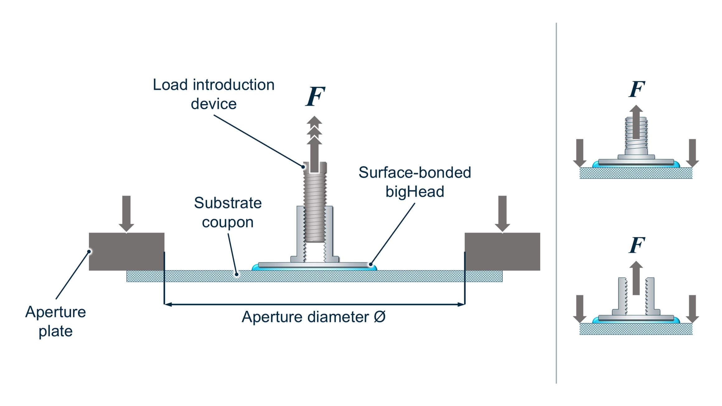
Pull-off test arrangement (surface-bonded collar shown) + typical loading arrangement thumbnails for blind surface bonded stud and collar installations
- Configuration: surface‑bonded fasteners in a blind arrangement.
- Objective: Determine the axial tensile strength across the adhesive-substrate-fastener interface.
- Principle:
- Fastener passes through the aperture.
- Aperture plate restrains the substrate.
- Load (F) is applied to pull the fastener off the surface.
- Notes: Stud (M1/ SM1) products must have thread length (L) ≥ 15 mm to avoid thread stripping of loading devices during repeated testing.
Pull-out test
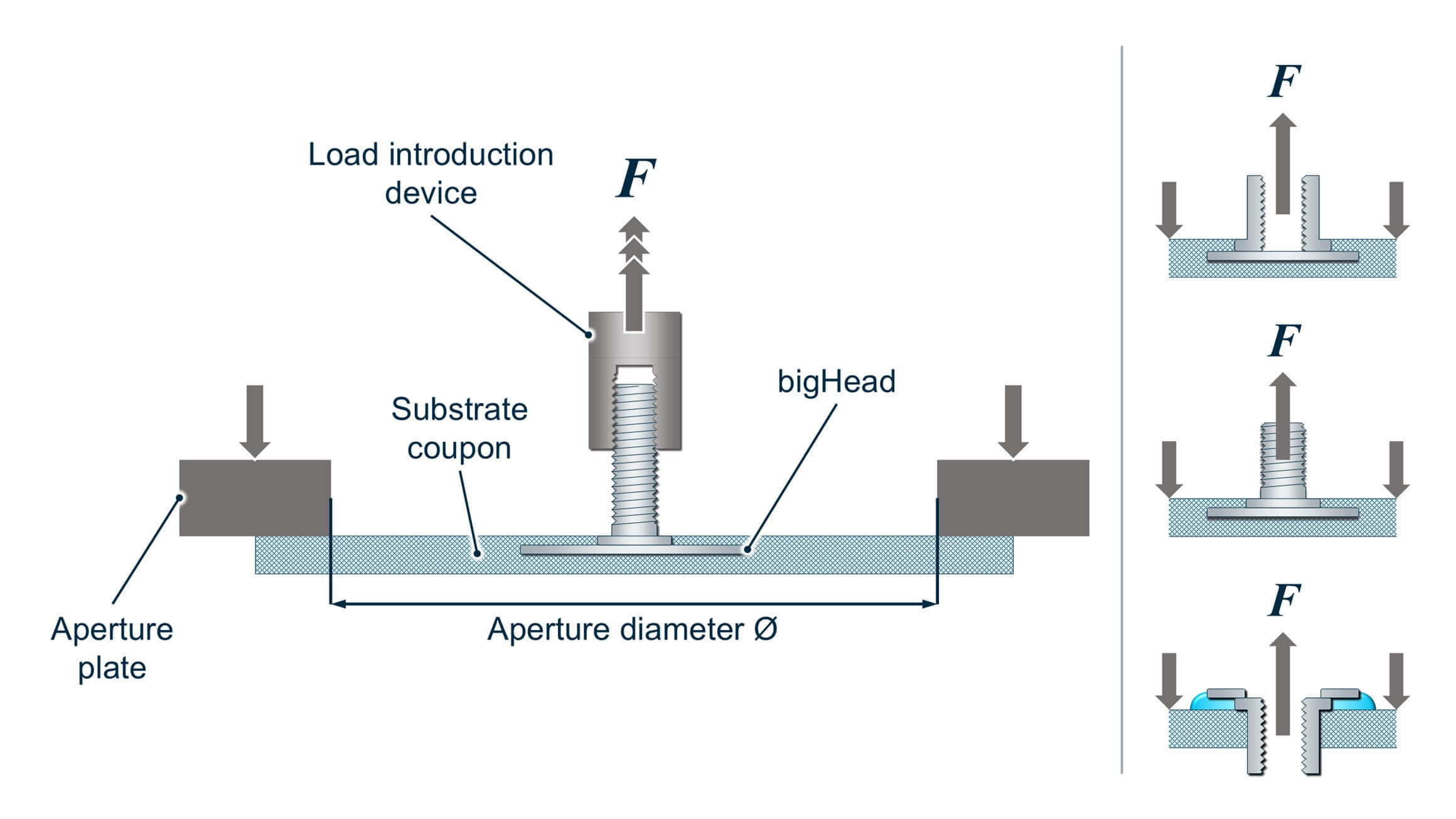
Pull-out test arrangement (embedded stud shown) + typical loading arrangement thumbnails for embedded stud and collar, and surface bonded socket installations
- Configurations:
- Embedded installations
- Surface-bonded – socket installations (screw entry through sighted Head).
- Objective: Measure axial strength opposite to the embedment direction (embedded), or screw entry direction (surface bonded – socket).
- Principle:
- Fastener passes through the aperture.
- Load (F) applied to pull the fastener out of the substrate.
- Notes:
- High-strength substrates may exceed load device capacity when testing internally threaded bigHead products.
- This is expected behaviour. In such cases, ultimate strengths cannot be determined.
Pull-through test
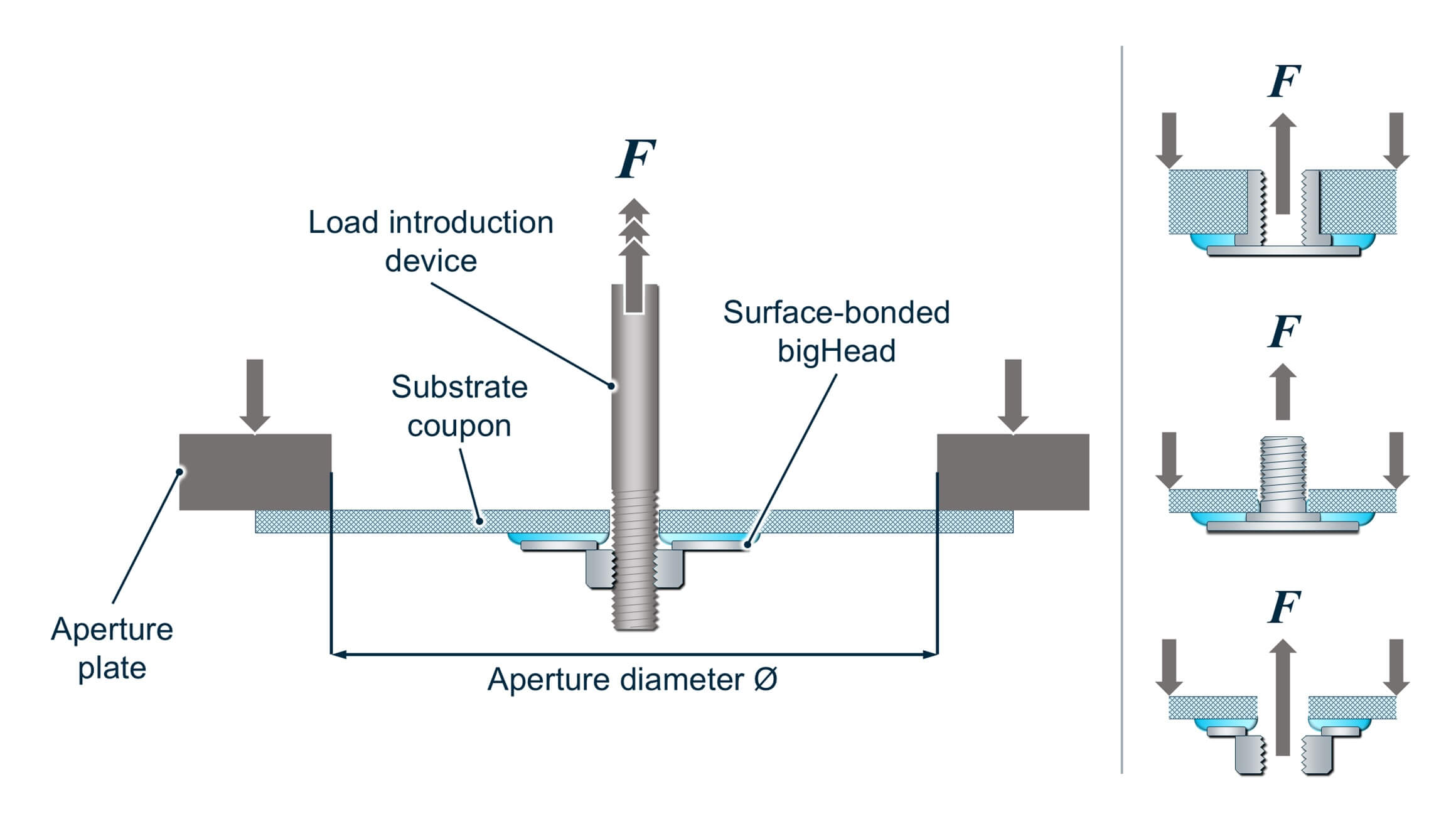
Pull-through test arrangement (surface-bonded nut shown) + typical loading arrangement thumbnails for through bonded collar, stud and nut installations
- Configuration: Internally threaded fasteners in through‑bonded installations.
- Objective: Determine resistance to axial loading opposite to screw entry.
- Principle:
- Load device passes through aperture and coupon.
- Load device engages with the bigHead fastener.
- Fastener is pulled (F) through the coupon.
- Notes:
- High‑strength substrates may exceed load device capacity.
- Substrates may fail by catastrophic fracture or flexural ‘crowning’ through the aperture, before fastener pull-through occurs.
- Both are expected behaviours. In either case, ultimate strength may not be measurable.
FAQs
-
What do axial tests measure – are they testing the bigHead fastener itself?
-
Why are there three axial test methods?
Each method corresponds to a different installation configuration and axial loading direction.
Depending on the configuration, the fastener, substrate, and adhesive (where used) contribute differently to the mechanical performance of the fastening system. Therefore, results cannot be compared between the three test methods.
-
Why do loading arrangements differ between the test methods?
To ensure the fastening system is loaded in a way that reflects real-world behaviour.
-
Why do axial test results vary between apparently similar samples?
Small differences in substrate composition, adhesive coverage, cure quality, or installation alignment can significantly affect axial strength and failure mode.
-
Why must aperture and coupon sizes follow the specified dimensions?
Correct sizing ensures the fixture properly supports polymer and polymer-composite substrates, and keeps results comparable across different bigHead Head types.